RMT-PILL Instruction Manual

Written by Jordan Huby
Updated at July 21st, 2025
Table of Contents

Instruction Manual
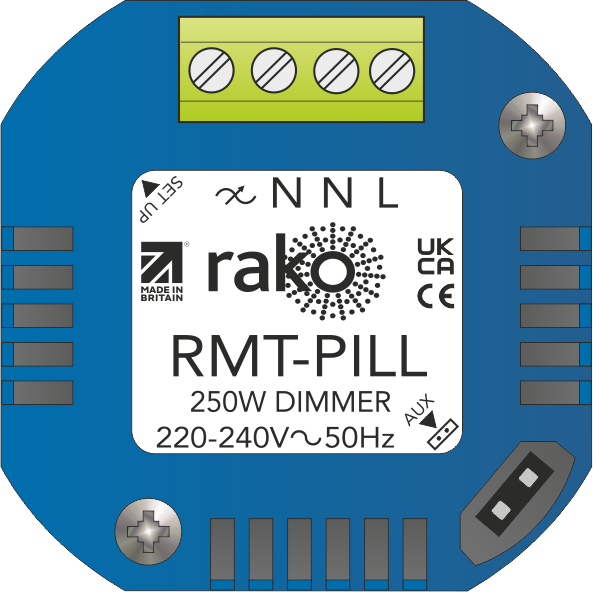
RMT-PILL
250W Trailing Edge Wireless Dimmer

2025
Version 2.0.2


Contents
3.0 Installation of the RMT-PILL 3
6.0 Programming the RMT-PILL 4
7.0 Appendix 1: LED Diagnostics 6
1.0 What is the RMT-PILL?
The RMT-PILL trailing edge dimmer is suitable for mains dimmable LED or halogens. It is intended to be installed in a backbox as a retrofit solution.
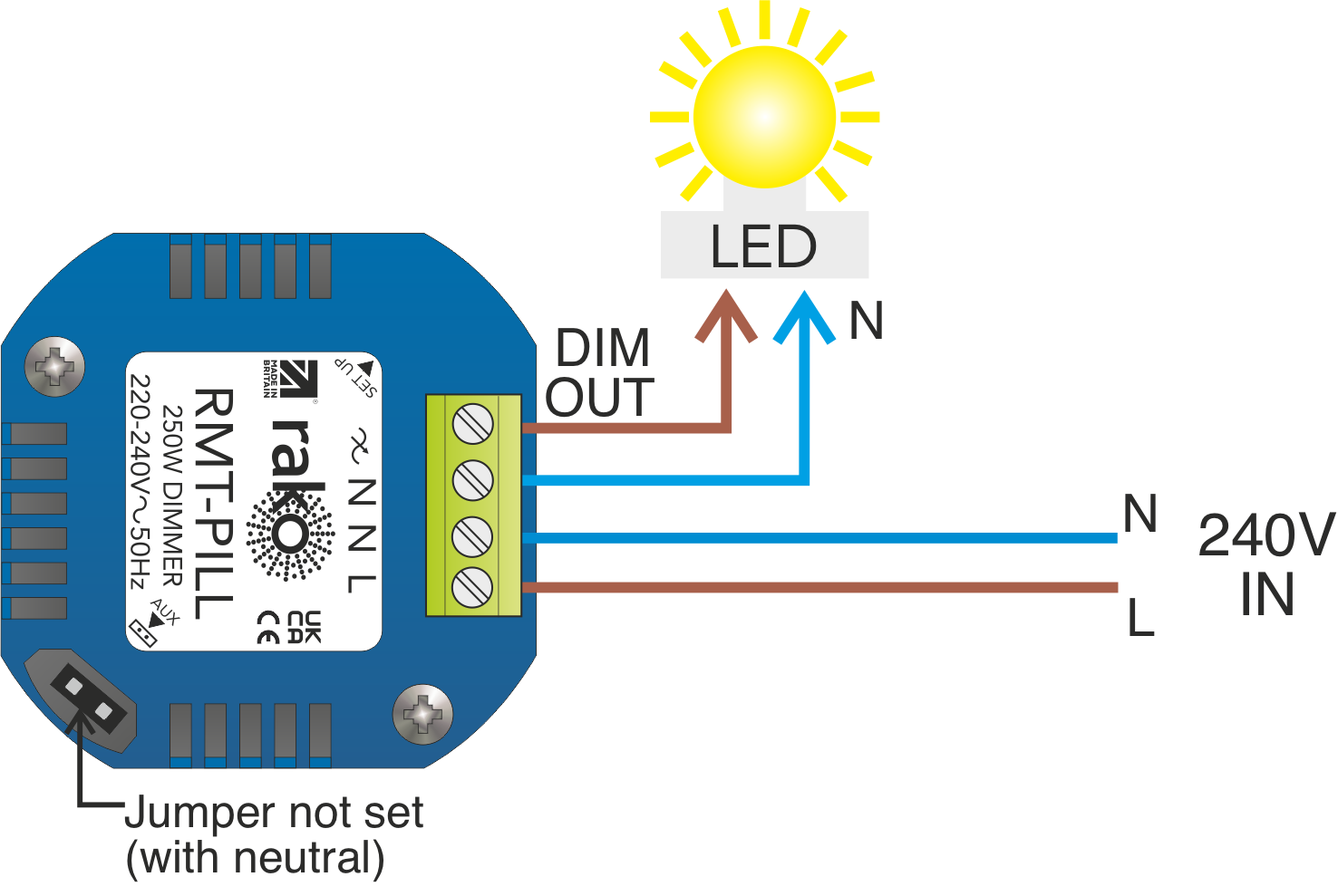
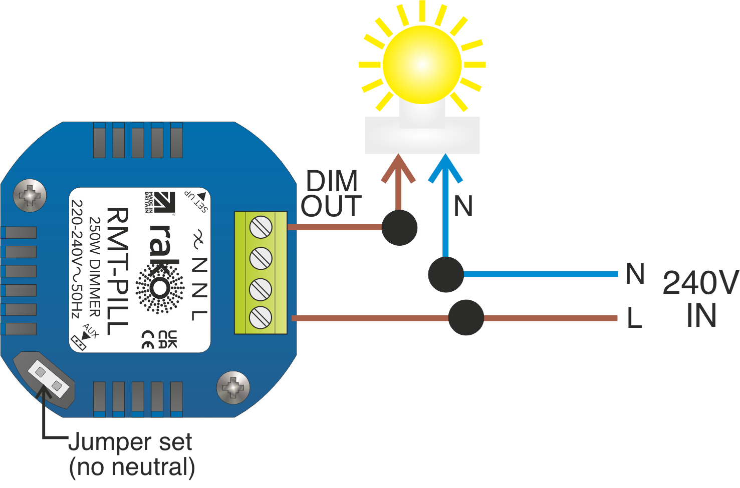
Depending on the fittings used in conjunction with the RMT-PILL, it can be used with or without a neutral connection.
RMT-PILL modules can be controlled by any Rako device that transmits wireless messages.
NB
The RMT-PILL dimmer module is not suitable for inductive loads such as wire-wound transformers or electric motors. Connecting these loads will cause damage to the unit.
2.0 Loadings
3.0 Installation of the RMT-PILL
Installation should only be carried out by a competent electrician.
- The module should be mounted in areas that are adequately ventilated, dry, and outside of any enclosed metal casings that may interfere with the wireless signal.
- While the modules are designed to be maintenance-free, they should be mounted in an accessible location should investigation or re-addressing of the units be necessary.
- Allow for additional space inside the backbox for cables and the unit.
- A neutral should be used whenever possible to optimise dimming performance.
- The RMT-PILL is designed to be mounted in an earthed electrical back box or conduit box. If a metal back box is used, then the aerial should be mounted outside of the back box into the wall.
- Without a neutral, the RMT-PILL can only be used with mains voltage tungsten halogen and not mains voltage LEDs. It is not suitable for low-voltage or any other transformer-fed lighting types.
- Only use the dimmer with either both neutrals connected or neither. Wiring a single neutral risks damaging the dimmer.
4.0 Auxiliary Input
The auxiliary input can be used in conjunction with a third-party switch to control the load without the use of a Rako wireless command. The required 2.54 pitch header connector is not included.
NB
Rasoft Pro and a suitable Communication Device (RAMPI/HUB) are required to enable the auxiliary input.
5.0 Initial Checks
- When power is initially connected to the module, the load should power up to full brightness.
- The internal LED behind the vent should flicker when the module receives any Rako wireless message.
- Should the module not respond to any of the above, then further investigation must be made before proceeding further.
6.0 Programming the RMT-PILL
Once the RMT-PILL has powered up and has been tested working with the setup button, the device is ready to be programmed.
Programming using a RAMPI or HUB using Rasoft Pro
Programming using an RCM Keypad
Programming With An RCM Guide.
For further general information relating to the RMT-PILL, see the Wireless Module Application Sheet.

7.0 Appendix 1: LED Diagnostics
Should the module not respond to any of the above, check the supply voltage.
For additional diagnostic information, see the Wireless Device LED Diagnostics.