RMT-1200 Instruction Manual

Written by Jordan Huby
Updated at July 21st, 2025
Table of Contents

Instruction Manual
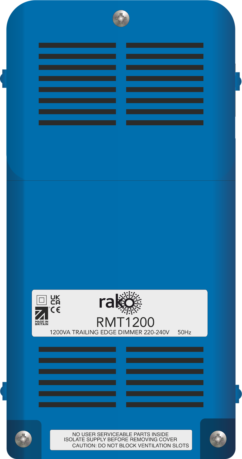
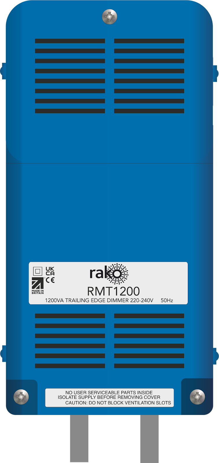
RMT-1200
1200W Trailing Edge Wireless Dimmer

2025
Version 2.0.1


Contents
3.0 Installation of the RMT-1200 3
5.0 Programming the RMT-1200 5
6.0 Appendix 1: LED Diagnostics 6
1.0 What is the RMT-1200?
The RMT-1200 is a trailing edge dimming module designed for mains dimmable LED’s and trailing edge dimmable loads.
RMT-1200 dimmers are not suitable for inductive loads such as wire-wound transformers or electric motors.
2.0 Loadings
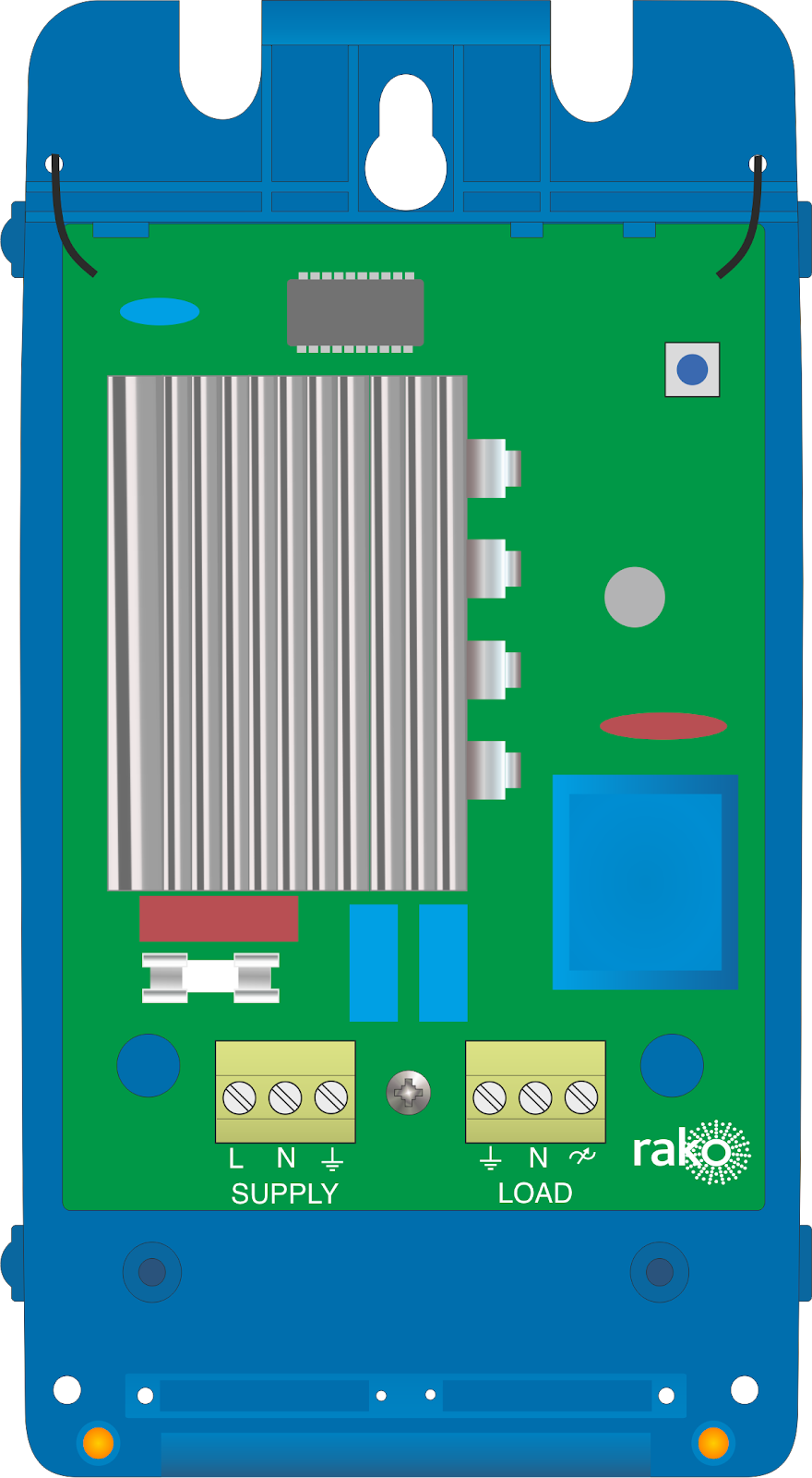
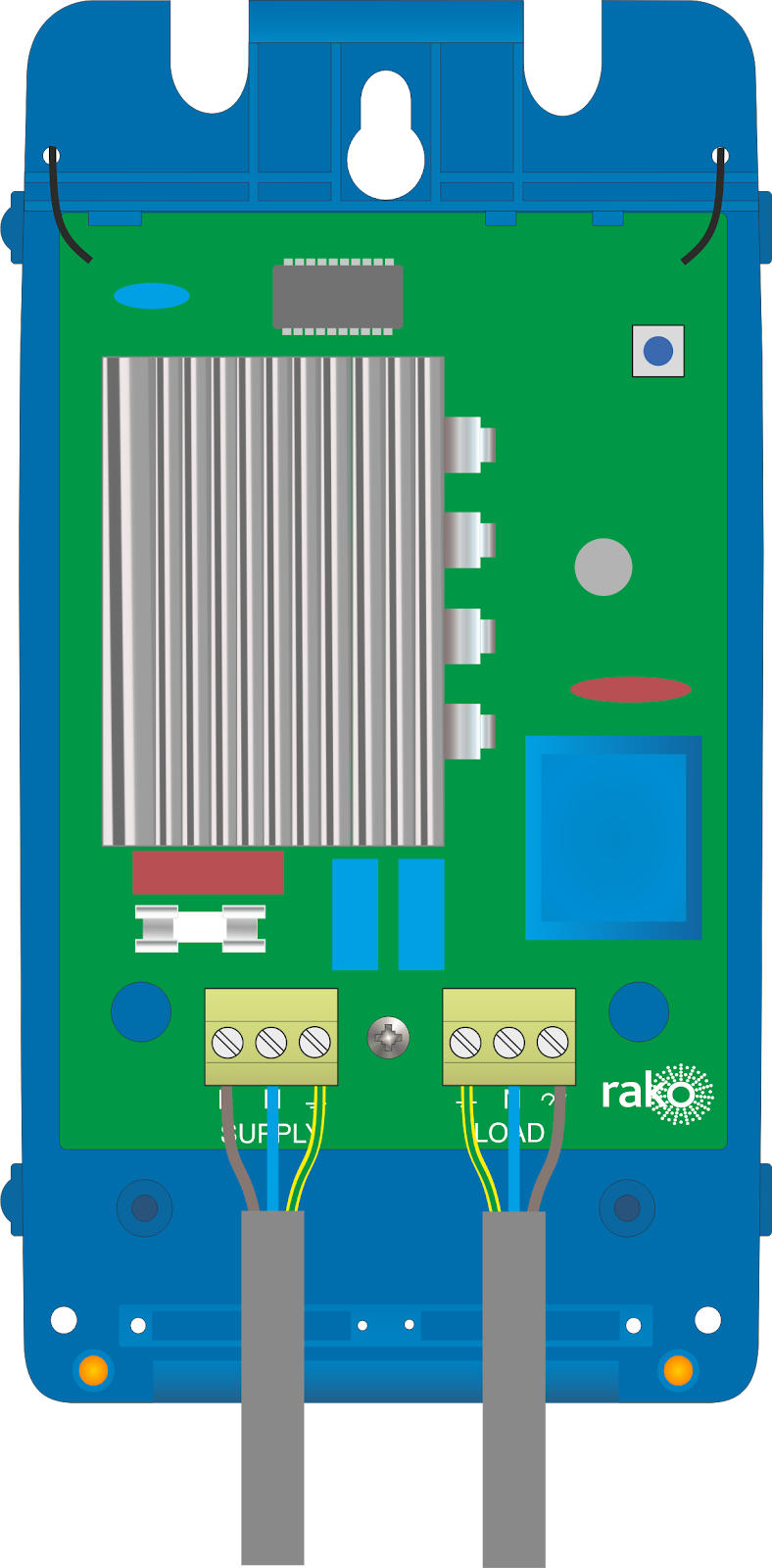
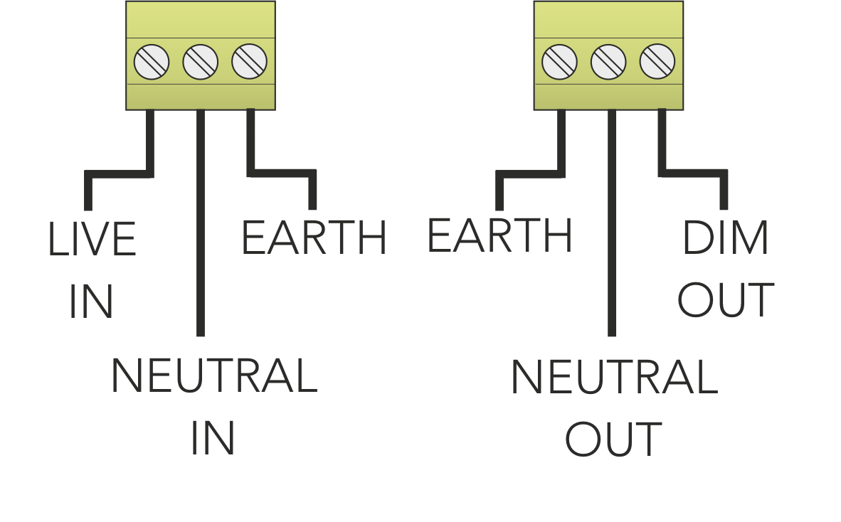
3.0 Installation of the RMT-1200
Installation should only be carried out by a competent electrician.
- RMT-1200 modules should be mounted in adequately dry and ventilated areas outside of any enclosed metal casings that may interfere with the wireless signal.
- Modules should be mounted vertically, with the terminals at the bottom.
- Ensure that cable clamps are securely fitted on the supply and load cables.
- While the modules are designed to be completely maintenance-free, they should be mounted in an accessible location should investigation or re-addressing of the units be necessary.

4.0 Initial Checks
- When power is initially connected to the module, the load should power up to full brightness.
- The button on the top right of the unit can be used to put the device into set-up mode as well as to toggle the load on and off for testing purposes.
- The LED on the circuit board flashes four times when the module receives any Rako Wireless message, and it is a useful diagnostic indicator. This function becomes inactive after 20 minutes to avoid a nuisance light spill but can be reactivated by pressing the setup button. For more information on LED diagnostics, see 6.0 Appendix 1: LED Diagnostics.
5.0 Programming the RMT-1200
Once the RMT-1200 has powered up and has been tested with the setup button, the device is ready to be programmed.
Programming using a RAMPI or HUB
Programming using an RCM Keypad
Programming With An RCM Guide.
For further general information relating to the RMT-1200, see the Wireless Module Application Sheet.

6.0 Appendix 1: LED Diagnostics

Should the module not respond to any of the above, check the supply voltage.
For additional diagnostic information, see the Wireless Device LED Diagnostics